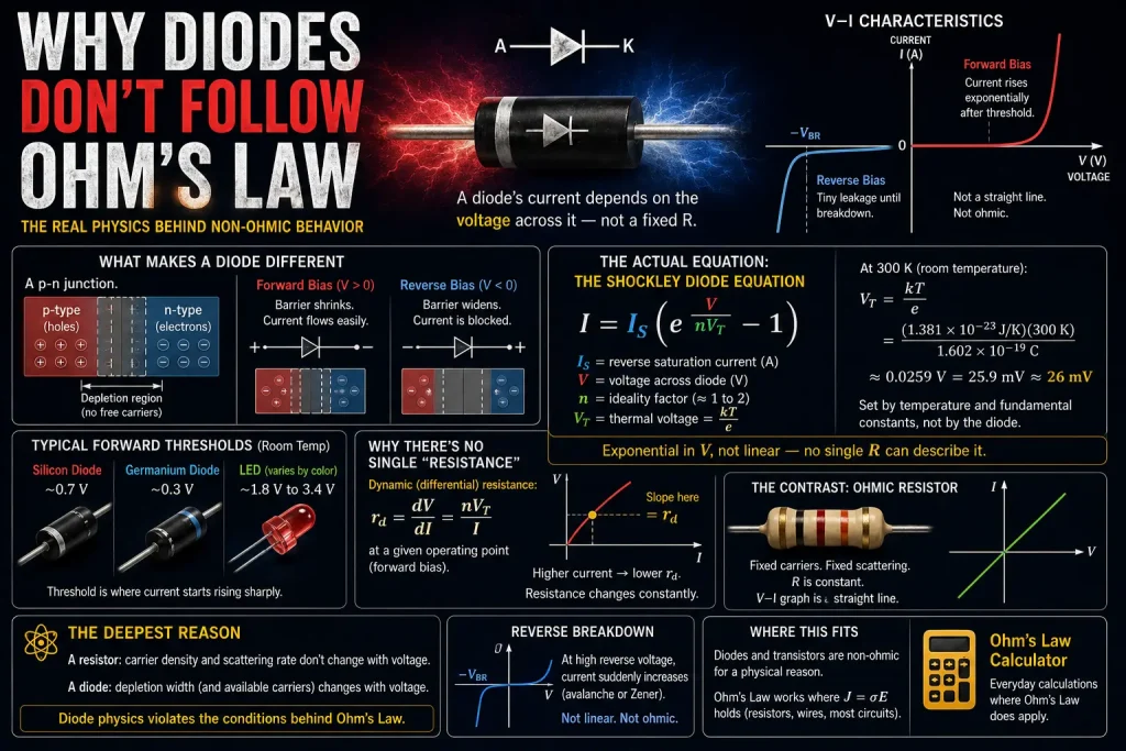
A diode’s resistance isn’t fixed; it changes depending on how much voltage is across it, which is exactly why Ohm’s Law can’t describe one with a single R value. Where a resistor’s V/I ratio stays constant no matter what voltage you apply, a diode’s current rises exponentially once forward voltage crosses a threshold, and drops to nearly nothing in reverse. This article covers why, down to the actual equation that describes it.
This is the semiconductor counterpart to Why Superconductors Break Ohm’s Law, two completely different ways of breaking the assumptions behind the Drude model derivation that makes ordinary resistors ohmic in the first place.
What Makes a Diode Different From a Resistor
A resistor is built from a material with a fixed number of charge carriers and a fixed scattering rate, which is exactly why its resistance stays constant, the two conditions behind Ohm’s Law holding true. A diode is built from a p-n junction, where the number of available charge carriers actively depends on the voltage applied across it. That single difference is the entire reason a diode doesn’t follow Ohm’s Law.
A p-n junction joins two differently-doped semiconductor regions: p-type material, doped with impurities that create mobile “holes” (missing electrons that behave like positive charge carriers), and n-type material, doped with impurities that contribute extra free electrons. Where the two regions meet, carriers diffuse across the junction until a depletion region forms, a zone with no free carriers and a built-in electric field opposing further diffusion.
Forward Bias, Reverse Bias, and Why Current Isn’t Linear
Applying voltage in one direction shrinks the depletion region and lets current flow easily; applying it in the other direction widens the barrier and blocks nearly all current, an asymmetry no fixed resistance value could ever describe.
Forward bias connects the positive terminal to the p-side and the negative to the n-side. This reduces the built-in barrier, and once the applied voltage crosses a threshold, about 0.7V for silicon diodes, roughly 0.3V for germanium, and anywhere from about 1.8V to 3.4V for LEDs depending on the semiconductor material and color, current rises sharply and continues climbing fast with only small further increases in voltage.
Reverse bias does the opposite, widening the depletion region and blocking current almost entirely, aside from a tiny leakage current from minority carriers. Push reverse voltage far enough, and the junction reaches breakdown, a sudden jump in current through avalanche or Zener mechanisms, depending on the diode’s design.
None of this resembles a straight line through the origin, which is the entire geometric meaning of “ohmic” behavior. A resistor’s V-I graph is one straight line; a diode’s V-I graph is flat near zero, then curves sharply upward, the visual signature of a non-linear device.
The Actual Equation: the Shockley Diode Equation
The relationship between voltage and current in an ideal diode follows the Shockley diode equation:
I = I_S × (e^(V / nV_T) − 1)
I_S is the reverse saturation current, the tiny leakage current that flows under reverse bias. V is the voltage across the diode. n is the ideality factor, typically between 1 and 2 depending on the specific diode’s construction. V_T is the thermal voltage, a quantity set entirely by temperature: V_T = kT/e, where k is Boltzmann’s constant and e is the electron charge.
At room temperature (about 300K), V_T works out to roughly 26mV, a number worth deriving directly rather than just citing: (1.381×10⁻²³ J/K × 300K) / 1.602×10⁻¹⁹ C ≈ 0.0259V, or about 26mV. That figure shows up constantly in semiconductor physics because it’s set purely by temperature and fundamental constants, not by the specific diode.
This equation is exponential in V, not linear; the mathematical reason a single fixed R can never describe a diode’s behavior the way it describes a resistor’s.
Why There’s No Single “Resistance” Value
Because the diode equation is exponential, both the static resistance (V/I at any point) and the dynamic resistance (the local slope of the curve) change constantly as voltage changes, and engineers actually use the dynamic version for real circuit design.
Dynamic resistance, r_d, is the derivative of voltage with respect to current at a specific operating point: how much the voltage changes for a small change in current, right at that point on the curve. Differentiating the diode equation, for forward voltages large enough that the −1 term becomes negligible, gives a clean result:
r_d ≈ nV_T / I
At higher forward current, dynamic resistance drops; the diode “gets easier” to push more current through as more current already flows. This is the opposite of how a resistor behaves, where resistance stays fixed regardless of current. Circuit designers use this dynamic resistance value directly when biasing diodes and transistors near a specific operating point, since it’s the only meaningful “resistance” a non-linear device actually has at that instant.
The Contrast With an Ohmic Resistor
A standard resistor holds a fixed number of free carriers and a fixed carrier scattering rate regardless of applied voltage, exactly the two assumptions behind the Drude derivation of Ohm’s Law. A diode violates both: the depletion region’s width, and therefore the number of carriers able to cross the junction, changes directly with applied voltage. That’s the deepest reason a diode isn’t ohmic, not that engineers arbitrarily decided to treat it differently, but that its underlying physics doesn’t match the conditions Ohm’s Law requires.
Resistors themselves, the components that do reliably follow Ohm’s Law, are usually identified by their color-coded bands, a completely different system from anything in this article, since a resistor’s value is fixed by manufacturing rather than by the physics discussed here.
Where This Fits
Ohm’s Law works reliably for the enormous range of components where current density scales linearly with the electric field, which covers the vast majority of practical circuit design. Diodes and transistors sit outside that range for a specific, well-understood physical reason, not because Ohm’s Law is unreliable in general.
For the everyday calculations Ohm’s Law does handle, including LED resistor sizing, which uses a diode’s known forward voltage alongside simple linear resistor math, the Ohm’s Law Calculator covers the practical side directly.